Nodes
Nodes are used to define the ends of members and plate corners. Nodes are also used to specify boundary conditions, diaphragms, story drift locations, and nodal loads. Each node is a point in space defined by coordinates in the global X, Y, and Z directions and temperature that may be used in conjunction with thermal loads.
Nodes can be input manually, or they can be created automatically as you draw new members and plates on the drawing grid. Once defined, the nodes can be edited in three ways: graphically, in the Node Properties Panel, or in the Node Coordinates spreadsheet.
Define Nodes
To define Nodes:
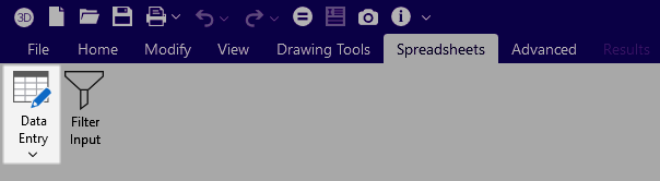
- Select the Node Coordinates spreadsheet from the Spreadsheets tab
 Data Entry button or from the Data Entry portion of the Explorer panel.
 - Define the node coordinates and temperature.
- You may use cut and paste, block fill, and block math to enter and edit nodes.
- You may choose the prefix that is used to label the nodes.
- To modify one node you may click that node in the 3D View to view and edit its properties in the Properties panel.
Relabel Nodes
- After sorting the Node Coordinates spreadsheet into the desired order, go to the Modify ribbon.
- Click the Relabel All or Relabel Selected icon.
- Choose Nodes.
-
Alternatively, you can right-click in the Node Coordinates spreadsheet and select either Relabel All Nodes or Relabel Selected Nodes.
Alternatively, you can right-click in the Node Coordinates spreadsheet and select either Relabel All Nodes or Relabel Selected Nodes.
Round-Off Node Coordinates
To round-off Node Coordinates
- go to the Modify ribbon.
- Click the Round Off Coordinates icon.
Alternatively, you can right-click in the Node Coordinates spreadsheet and select Round Off Node Coordinates.